Gear Pair and Spline Pair design modules

The Gear pair design tools give you the flexibility, freedom and confidence to bring your vision to reality, easily and quickly. Gear pair design offers you the following features

 | Gear Pair Design (Involute only) |
| | External, Internal, spur and helical. |
| | Major tolerance standards, AGMA, DIN, ISO, JIS, GB and user defined |
| | Design new pair or design mate based on existing part or design master gear |
| | standard and non-standard center distance |
| | Depth system |
| |  | User defined |
| | | Full Root Radius |
| | | Pre-Shave Standard |
| | | Fellows Standard |
| | | Fellows Stub |
| | | Fine Pitch Standard |
| | | Old American Standard |
| | | AGMA Stub |
| | | PGT-1 Tooth Form |
| | | PGT-2 Tooth Form |
| | | PGT-3 Tooth Form |
| | | PGT-4 Tooth Form |
| | Tooth size methods |
| | | Chordal tooth thickness |
| | | Normal circular tooth thickness |
| | | Measurement over balls |
| | | Span measurement |
| | | Normal backlash |
| | Tooth height methods (Enlarged or reduced profile) |
| | | Addendum |
| | | Tip Diameter |
| | | Shift Factor X |
| | | % Over Size |
| | Start of Active Profile (SAP) |
| | | Calculated |
| | | User Input |
| | Track design variations |
| | Design gear pair based on existing 'Common' tools |
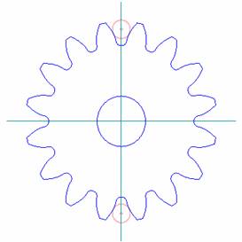
| | Graphics Visualizer help to spot design flaws and provide design warning messages. |
| | | Dynamically show pair meshing in action |
| | | Graphics show teeth contacting, to show interference if any |
| | Revision History |
| | Secured design approval |
| | Export pair design to Text/Excel/PDF files |
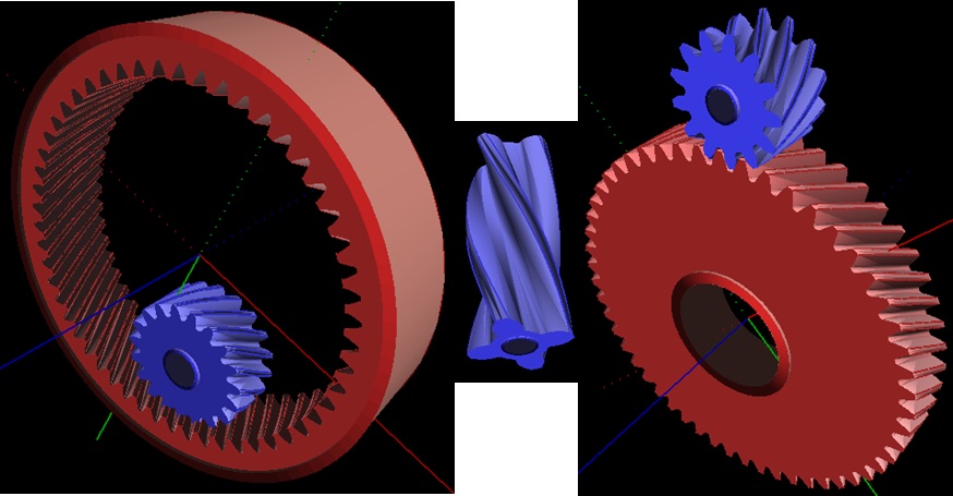
Gear Pair design examples
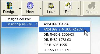
Spline Pair Design
Simple steps to walk you through the spline pair design quickly, Spline Pair design provides the following features
| Spline Pair Design (Involute only) |
| | External and Internal Splines |
| | Spline design standards |
| | | ANSI B92.1-1996 |
| | | ANSI B1992.2M-1980 (R1989) |
| | | DIN 5460-1:2006-03 |
| | | DIN 5482-1973-03 |
| | | JIS B1603-1995 |
| | | BS 3550-1983-09 |
| | Design new pair or design mate based on existing part |
| | Track design variations |
| | Design spline pair based on existing 'Common' tools |
| | Revision History |
| | Secured design approval |
| | Export pair design to Text/Excel/PDF files |
Spline Pair design examples
Data exchange, document automation and Engineering CAD drawing supports


Gear/spline, either single or pair, process data and associated cutting tools data, which can be packed into one XML file for exporting and importing to other subsidiary of organization without re-entering the information. XML export/import capability makes inter-organization collaboration and communication easy and supply-chain management system feasible.
Document automation, easy to produce detailed and insightful reports in Text/Excel/PDF/XML/DXF/IGES files for Gears/Splines and Cutting Tools for shop drawing, machining, documentation and information exchange.
Engineering CAD drawings in DXF or IGES
Complete Gear/Spline drawings in 2D (DXF, IGES) and 3D (IGES)
Paste Gear/Spline images to any windows graphic format for easy documentation.
Band fit(Lead or Profile) in DXF format for engineering drawing
Process notes in DXF formats for engineering drawings
CAD DXF examples
Engineering CAD file in DXF or IGES with extended applications
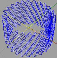
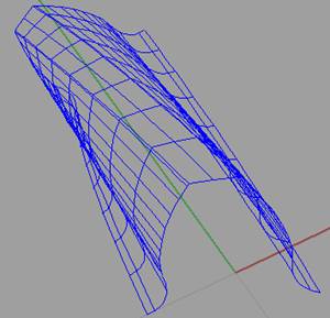
CAD IGES 3D examples
2D Tooth in DXF creates the profile in a series of arc forms that are generated based on selected Hob or Shaper, ideal for CNC milling, form cutting, form grinding or EDM
3D IGES complete gear models for CNC milling or RAM EDM
3D IGES Tooth models for FEA or CNC milling
|